3D Modeling - Exercises
24/04/2024 - 05/06/2024 / Week 1 - Week 7
Adriena Tan Yan Zi / 0351236
3D
Modelling / Bachelor of Design (Hons) in Creative Media
Exercises
.jpg)
Lectures
Week 1:
3D animation: Pre-production - Production - Post production
3D modeling
Texturing
Rigging
Animate
Lighting
Rendering
- Quad view = ctrl + alt + Q,
- press N for side bar
- Press T to bring out the left tool box
- click move tool to move object
- Alt + G to reset position +(press x, y, z)
- Alt + R to reset rotation +(press x, y, z)
- Press S for scaling
week 3:
- Press I for inset
- Press E to extrude
- We can press S to scale on the extruded part
- ALT + click to select everything
- Press look up in edit mode and scale mutiple times to make curved line
- For a curve smooth side, we can you bevel, then go to EDGES on top, Bevel edges and setting below to adjust many section you want, the width as well
- ctrl + B to bevel edges
- ctrl + 1, ctrl + 2, ctrl+3 to change into a higher polygon
- press e, right click to cancel the press s and move up
- to add thickness you can add solidify at the modifier side and add thickness


We were thought how to make a plastic bottle in high polygon and low polygon in class.
Week 4:
- ctrl + B to bevel
- press J to connect vertex path (vertex - connect vertex path)
- to bevel evenly, go to object mode - selct object - apply - scale (all the scaling should be on 1.0)
- shift + alt to select the edge to select horizontal.
- Colour: Select edges - right click - mark saem - material - +new - colour - assign
- Ctrl +L to select the whole MARK SAEM
week 6:
- Go to edit, preferencesand addon. The type bool tool and tick the box. You will have an option on the sidebar.
- to join 2 shapes together we go to object mode, with object tab, press join or ctrl + J.
- then go to edges and bridge edge loop.
- add modifier, subdivision.
- select vertices and press G ti connect vertices.
- I need to add loop cut to both side of the edges that i want to stay sharp as I apply high polygon or shade smooth

week 7:
Got to scene at the side, and pick eevee or cycle to render your image.
Go to render and render image.
to adjust the lighting, we can select the lighting and go to data to adjust the type of light we want at the right panel.
We need to split screen, and select a face. Change 3D viewport to shader editor.
Go to edit, preferences, find wrangles in the search bar and ctrl + T.

Instructions
Exercises
Sketching


EXERCISE 1 - PRIMITIVE MODELLING
1st model - wooden person

Since I had already planned out the model i wanted to do beforehand, I just
insert the first few meshes i needed which i a sphere and a loop.

With the pill mesh i managed to build the bodies to see how becaus ei find it
worked better than the cylinder.


From here on, i used the cone shape for the girl's lower body and used the
cylinder mesh to build the legs.

For knee joint i used a sphere to mimic the real wooden model.


Added the shim to find that it looked to robotic to I sculpt it a little bit,
to make the proportion look more realistic like a doll and more
accurate.


Moving on to the limbs, I used similar mesh to build the arms, fixed the
proportions, tweak it bit before i added the hand of the model.
2nd model


Next i'm making a castle for this girl so i stared ogg with basic meshes like
cylinders for the poles and cubes for the walls.

I'm trying to view the castle from the side view to build the walls here and
align the poles correctly as there will be 2 poles on the inside for the
castle.

Referring back to my sketch, I added the top part of the castle and used a
cone shape as the roof of the castle. Moving on to building the front gate of
the castle, i once agin started with poles to support the walls and main
gate.


I building the design of the balcony part on top od the pole and made sure
they have a fence like normal castles would have. Doing this from the top view
and rotate the tiles so will align evenly.


For the gate as im not sure how to make the shape curve to mimic the shape of
a window or the main gate, I had to search up a tutorial to do this.

Once all the basic structure are done, I moved on to putting tiles on the wall
surface so it would look more like a old stone wall.
Final Exercise 1

Final rendered castle and human.png

Final rendered castle and human with wireframe.png
EXERCISE 2 - MODELING FROM CYLINDRICAL SHAPE


With the experience and technique i learned while modelling the ater bottle, I
got to familiarise myself with the use off the tools taught to us that dat
which was inert, extrude, bevel and loop cut. I started off with a tigre fan
cylinder and removing the top surfaces leaving onlt the base to start buding
the wine glass.


When the wine glass shapes took shape, I apply the high fidelity to achieve a
smoother surface for the other types of glasses by pressing ctrl +1 and ctrl +
2 to achieve the appearance of the above.


Then i got an idea from the example shown in the assignment google doc to make
a round bottom wine glass which is the most common ones on the market. I then
started agan with a tigre fan cylinder with lesser sides this time.


For this part i used the simple scaling, extrude and inert tool to achieve the
stem of the wine glass before proceeding to making a curves suface cup with
the extrude and scaling tool.


Other than wine glasses, I wanted to added some wine bottles that come in
different shapes and sizes to compliment the whole presentation of the models.
As you can see above, i experimented with several different shapes wine
bottles to see which ones suits best with the rest of the wine glasses.

As I change the wine bottles quality to a high fidelity or even smooth
surface, I noticed that the creases that were supposed to identify the
placement of the bottle cap is smooth out into the rest of the bottle which
made it hard to tell it was a wine bottle. To fix this, I recalled sir
teaching a method which is to use loop cut to cut where you want the crease to
be and apply mean crease at the tranformation panel.

Lastly to refine the rendering and final presentaiton, I added colour, made
some of them metalic and applied shadow so it looks more realistic.
Final exercise 2

Final wine bottles & glasses.png

Final wine bottles & glasses with wireframe.png
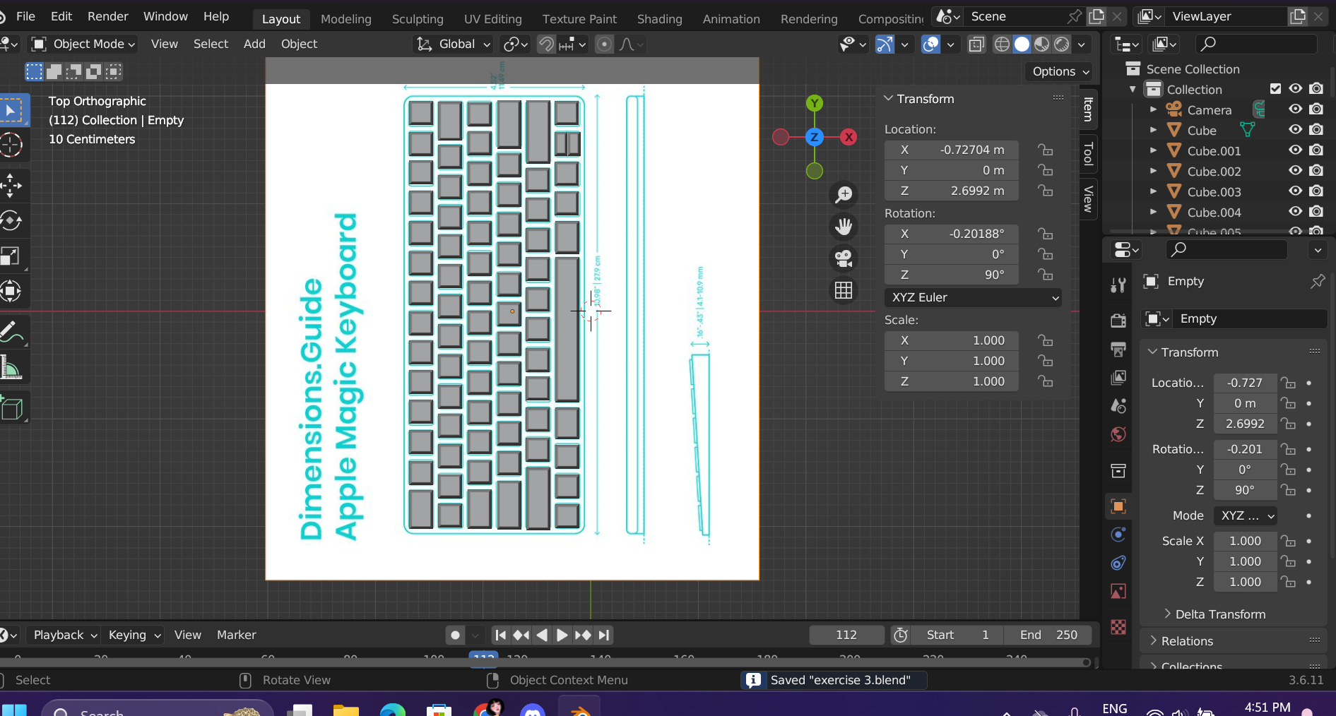
EXERCISE 3: MODELING FROM BOX SHAPE
Selecting the reference blueprint

We have the freedom to pick whatever it is that we wanted to model out of a
cube. I did some research and was contemplating between a gameboy or a
keyboard, in the end i deciided to go for the keyboard as I would like to
colour each key of the keyboard differently. I figure making this would be a
good opportunity to put the fundamental tools in blender into practice.
.jpg)
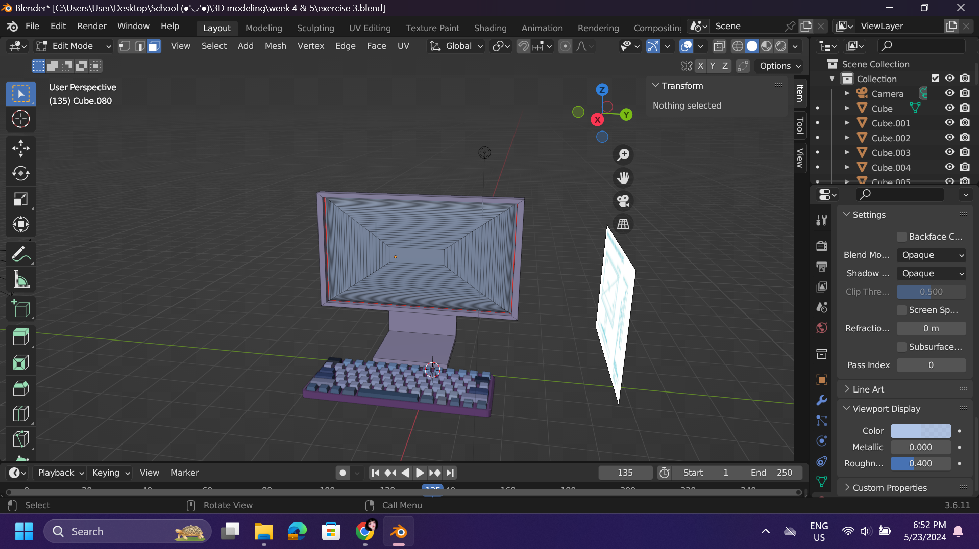
Initially I didnt think of modeling a monitor alongside the keyboard.
However, with the keyboard alone seems to be a little empty so I decided to
look for the blueprint of a modern monitor. This way I can pair them
together for this exercise.
1. Modeling the keyboard

Firstly, I started adding the cube mesh and scaling it so it would me
flatter to be a normal keyboard shape. Then using inset and extrude tool,
I'm able to make the base of the keys. I had a plan to loop cut the middle
section so I could get them to look like insividual keycaps.

Unfortunately , that did not work out quite how I like it to be so I moved
on to modeling the keycaps one by one with the cude, scaling and move tool.
Here I'm just aligning the keycaps according to the blueprint that I have
downloaded. Duplicating and change the length in edit mode as I go so each
of the kepcaps would fit properly.

When I'm finally done working on the keycaps, I had to give them a keyboard
base. I did so with the cube mesh and bevel the edges following the
blueprint.

Moving on, I noticed that the top part of the base keyboard is slightly
thicker than the rest of the keyboard to promote comfortable typing.
Following the blueprint, I added thickness to the necessary part.

Finally, I moved on to coloring the keyboard starting from the base to each
of the keycaps one by one since I made them seperately.

I had an idea to colour some of the keycaps different from the rest to add
to the visual appeal.

With the monitor blueprint as guide, I started off with screen and set it to
the desired length and width.

When the screenbase is set, I needed to model the frame of and the screen
which i used the handy dandy inset and extrude tool to create this.

I move don to modeling the hind part of the monitor whether it connects the
stand to the monitor. To achieve the stacking textute i have to inset ans
extrude a few times.

Using the move tool, I moved the middle inset up following the placement of
the blueprint with side view provided.

I had to use the move tool to tweak it a few times to get the result that i
wanted before i moved on to modeling the leg which is the main supposrt of
this monitor.


I used the bevel tool in edit mode to achieve a smooth and curved screen.
Finally, I coloured the monitor accordingly so it would matches the
keyboard.

Exercise 4 - Organic Modeling
Sir actually thought us how to make the enire Karambit in that day's class. I did mange to finish it but I didnt like how the blade part is crooked and the wireframe was so messey to I went home and reattempted the modeling again with the technique learnt in class.


Following the tuorial from the top of my memory, i made the handle with 2 cylinder mesh and difference it to create a hoop. Then i model the handle part using cube mesh and scale and move around with the scale and move tool to achive the curved shape for the handle.


Then I have to loop cut the handle dioganally to connect some of the selected faced to the hoop. Using the bridge edge loop, I manage to connect the handle and the loop just fine.


Following the reference picture, the connecting part is slightly dented inwards so I adjusted the dent with the move tool. Checking the wireframe as I go, so it wouldn't get too messy.


Then extruding from the handle part, we were thought to make the middle part first.


Then selecting the side surfaces, I used extruded along normal to achieve the full blade. As the sharp parts of the blade are thinner then the middle, I had to use the scale tool to make the sides of blade thin to appear sharp.


During tutorial, sir also thought us to move the wireframe of the tip part sharp towards the tip of the blade so the front part would look smoother and not chunky.

Lastly, I added loop cut to some parts that I wanted to stay sharp as I apply high polygon or shade smooth.


Feedback
Week 5: The car was nice, but i have to keep in mind to not duplicate
the faces or models by accident or the coloring woudn't show.
Week 6: For exercise 3, to smooth out the monitor screen, I can just
right click and shade smooth to achieve a smooth surface. Try to cover the
backgorund when I export the image.
Week 7: Something wrong with the modeling karambit, try to arange the wireframe better. he handle part is not model well. Can covert to high polygon.
.jpg)
.jpg)

Comments
Post a Comment